

Steps to Install a Satellite Dish
Step 1. Identify the parts
If the equipment has been purchased from several different vendors, small items like cables may not have been provided.
Immediately after receiving the equipment the installer must perform a full inspection; missing items can be identified and ordered while the initial work of installation is proceeding.
The procedures shown here demonstrate how to install a larger antenna than most of our customers need, it is still useful to view these procedures because they still apply to the smaller antennas, but with less weight of concrete required.
Choose the placement position.
Before commencing installation it is wise to find the compass bearing and the elevation of the satellite. Either the US Teleport or the satellite operator will provide the settings for the compass bearing, and the degrees of elevation that are necessary for the antenna to hit the satellite.
Using this information the installer will confirm that there are no trees, buildings or other obstructions that prevent the antenna from having a clear view of the satellite.
Normally the antenna will be placed on the ground, or in some cases a roof, but as close as possible to the main building where the electronics and electrical power are housed. The greater the distance from the building, the higher will be the cost of the cables connecting the two together, but more importantly, each meter of cable introduces a slight loss in the signal, a long cable run can seriously impact the transmit capability of the antenna.
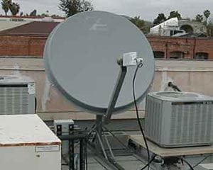
In our example we show the antenna being installed on a permanent concrete pad. There are other alternatives though, if the antenna may possibly be moved in the near future it can be installed on a non-penetrating mount. These systems are also called load frames and can be used on roofs where it is impossible to dig and pour concrete.
Even though the larger antennas may sometimes sit on non-penetrating mounts, in Florida we are prone to high winds, and our installation of the Andrew 4.5M shown here was safely mounted on a solid concrete pad, but the smaller antennas of 3.8m or less can often sit on the roof of a building or on a firm flat piece of ground because they offer a smaller target for the high winds.
Bolt Together or Theodolite Antenna.
There are two types of permanent mount antenna, the simple type is normally called a “Bolt Together” the alternative in the larger antenna is referred to as a “Theodolite Style”. The difference between the two types refers to the way that the reflector panels are aligned. A bolt together antenna has panels that fit on the supports in a static way, in other words, put each panel in place and tighten the bolts. With a large antenna of 7 meters and above, the exact curvature of the reflector panels plays a very important part in its efficiency, and the reflector panels have several points on individual panels that allow the panel to flex and change shape.
One of the most common way of ensuring that the curvature of each panel is perfect is to use and instrument called a theodolite and allows very accurate adjustment of each panel to the best possible shape.
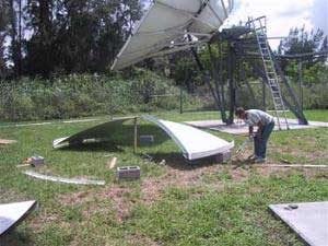 Assemble the reflector |
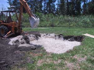 Digging the foundation |
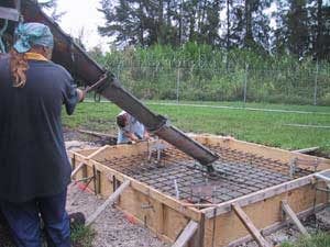 Pouring Concrete |
Part 2 – Aligning the antenna.
Step 3. Mounting the VSAT Equipment
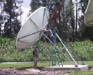
Building the antenna is time consuming, depending upon its size it may take from one day to three days. The larger antennas will need the help of a crane to position the reflector on the mounting supports. On the left you can see the reflector carefully guided into place, and loosely bolted into place, but the bolts that control the antenna position are always left loose to enable final alignment with the satellite.
Typically a transceiver or BUC is mounted on the antenna support frame, then the signal (IF) cables are connected from the antenna to the building where the modem and Internet routers are housed.
We recommend that our clients use a UPS between the main A/C power supply and the electronic equipment by the antenna. This is the best way to prevent damage in the event of power cuts or power surges.
Step 4. Antenna Alignment
In their orbit above the earth the satellites are located a few degrees apart, and so finding the target satellite can be a difficult task. A professional installer will find a satellite in a matter of a few hours. Installers with less experience may take weeks of frustrating effort before getting the correct alignment.
The final step in alignment is the Peak and Pole procedure. The satellite operator engineers look carefully at the signal being generated by the new site, and they will insist on correct alignment of the antenna and the polarizer in order to insure that the antenna is not interfering with adjacent satellites or with other poles on the same satellite.
Even though the larger antennas may sometimes sit on non-penetrating mounts, in Florida we are prone to high winds, and our installation of the Andrew 4.5M was safer being mounted on a special concrete pad, but the smaller antennas of 3.8m or less can often sit on the roof of a building or on a firm flat piece of ground.
In these photographs we show the installation of an antenna in a grass lot, but sometimes this is impossible. if you need to install on a concrete parking lot or on the roof of a building in you will first need to install a load frame and then the antenna is attached directly to the load frame.
 C-Band Antenna |
 KU Band Antenna |
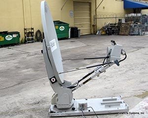 KU Band FlyAway |